- 1. Stock brand new friction plates are .167” thick and the steel plates are .065” thick.
With (5) friction plates and (5) steel plates, the thickness of the stack is 1.150”.
If you will sort through your box of old worn plates and pick out used friction that are otherwise
in good condition and between .120 and .130 in thickness, you will find that the stack of (6)
friction plates and (6) steel plates will be less than 1.150 and they will all fit in your basket.
To make additional room, I chiseled off the friction material on one side of the first friction plate,
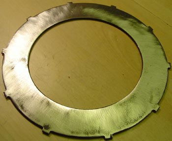
buffed it smooth, and slipped the smooth side into the bottom of the basket.
Make sure that when you fit the next steel plate the inner tabs are well engaged in the inner hub or
you will have problems. If that is the case, try installing an unmodified friction plate in the bottom.
This will give you a little more thickness so the tabs on the first steel will be comfortably engaged in
the center hub. There is a little in/out movement between the basket and the center hub because of the end
clearance in the rollers.
- 2. Alternately install the friction and steel plates (6 each). When they are all in be sure that the
last plate, a steel one, has its tabs engaged in the center hub and are not close to slipping out.
- 3. Install the pressure plate and springs. You can use CCM springs for more pressure. You may have to use
a little force to get the nuts started, as the whole plate stack is probably thicker than you are accustomed to.
I run the nuts down to so that the inside head of the nut is flush with the top of the cup and then spin the
assembly with the kick starter to make sure that the pressure plate is running reasonably true.
After the clutch is finally adjusted check to make it doesn’t slip when you try to kick over the motor
without using the compression release. Also check that it disengages as you pull in the clutch.
- 4. Try installing your clutch rod adjusting screw. It may not be long enough to set the clearance and still
get the jamb nut on. In that case make a new screw out of a Ľ-28 or a Ľ- 26 bolt (earlier model pressure plates
were BSF and from sometime after 1970 they were SAE. 71 and 72 models should all be Ľ-28 unless someone changed
the pressure plate. I took a 3/4 x Ľ-28 bolt, ground down the head till it was about 3/8ths diameter and then
cut a slot for a flat tip screwdriver in it with a dremel tool. I then shortened the bolt so it would not
interfere with the access cap, but left it long enough to get a jamb nut on it. Use a hardened bolt or harden
the finished bolt. Install it using the normal clutch setup procedure.
This clutch now has 11 driving surfaces as compared to 9 surfaces in the stock B50 clutch and 8 surfaces in
the b44/25 clutch. That’s 22% more driving force. Some claim that when a clutch starts slipping, the plates
get glazed and no longer provide enough driving friction. I don’t necessarily agree with that claim because a
brand new clutch slips the very first time you use it and it slips each time you pull the clutch lever to take
off or make a shift. It is made to slip. You can burn them up if you constantly slip the clutch under hard
load, but I think that as the plates wear down, you lose some of the spring pressure as they become less
compressed. Adding the additional friction and steel plates returns the plate stack to its original thickness
while adding two additional driving surfaces. You are also returning the spring pressure to its original
compression. If you have any questions please drop me an e-mail at mrmike@coastalnet.com.
I hope you have the same success I had with this little upgrade.
Mr Mike
I have done this. I took of the friction material with a racerblade and the grinded it with sandpaper.
I also welded the first steelplaet to the preasure plate, while everything is bolted together on the bench,
as I was voried that the steelplate should go outside the clutchcenter when using the clutch.
Rickard
© Rickard Nebrér
Updated 08:44 2006-04-12
6 plate Clutch by Mr Mike from the B50 forum.
“DRAFT”
Making a BSA Unit Single Six Plate Clutch
The unit single has a clutch that was originally designed for a 250cc machine.
Over the years there have been modest improvements to the original clutch to improve
its capability and prevent slipping especially in the B44 and B50 machines.
The original 250 was a four-plate clutch with 8 friction surfaces. The first plate
in the basket is a steel plate and the plates are alternated so the assembled clutch
has 5 steel plates and 4 friction plates, hence (8) driving surfaces for B25/44 models
since each side of the friction plate provides a driving surface.
Rupert Ratio provides a modification where you can cut off (in a lathe) the flange at the
rear of the hub, insert an additional friction plate into the bottom of the basket followed
by a steel plate and then alternating the plates with the last plate being a steel plate for
the pressure plate to ride against, this increases the number of driving surfaces by one to (9)
as the back of the first friction plate does not provide any driving force.
I have done this to my B44 and it cured slipping problems. It has the disadvantage of not having a
thrust washer between the hub adapter and the clutch basket. This will cause wear on the rear of
the basket whenever the clutch lever is pulled.
Along comes the B50 and it basically has the same clutch capacity (9) surfaces as the Rupert Ration
b44 modified clutch, but they have changed the hub adapter and added the thrust washer that is missing
in the Rupert ratio upgrade.
The following upgrade can be done to either the B44 with the flange removed or the B50 clutch: